Plume capture and Xenon Propellant Capture
Heavy xenon gas propellant capture from a Solar Ion or other Radiation Ion space craft is possible. To create propulsion, heavy xenon gas ions are transferred across a nozzle geometry and zapped with a charge that accelerates the xenon ion across a plasma arc which then neutralizes the ion.
As accelerated Xenon leaves the thruster it is pushed out at MXVT thus propelling the ship forward. This exhaust creates a distinct plume in a vacuum. Our capture apparatus would first have to take on certain geometry and length to capture the plume.
So how do we catch this xenon particle and absorb zero of its negative momentum? The momentum drive concept applies state and momentum physics to essentially capitalize on and control what naturally occurs with positive momentum geometries.
The exit nozzle on the space craft has a nozzle bell attachment. This bell provides shaped exit into space vacuum and keeps heat away from the spacecraft. For our capture module we attach to or replace this bell and create a plume capture volume. Through research and experiment we determine that the plume capture bell needs certain volume at its widest point which is shaped to be a distance from the exit nozzle at the given impulses.
As the gas particles exit the nozzle they are fast at MXVX and entering what they see as a space vacuum. Several things could slow this heavy xenon particle down. First we want to create some apparent vacuum turbulence and shaping of the particles. So immediately at our nozzle bell attachment we expand our radial diameter for a small curve shape and to a slightly larger diameter. We essentially normalize our exhaust plume and channel the possibility of catching our xenon atom.
Our expansion chamber contains a baffle system that the particles flow around appearing to them as heat or local turbulence. The purpose of this expansion chamber is to receive the exhaust to start shaping it and to keep the exhaust plume moving down the column. Their shape, location, material, and other cross sectional properties are experimentally determined to reduce backflow and provide tuning of the exhaust plume.
So let's say our gas molecule is still moving at a significant speed and momentum. After passing through the radial bell baffles the volume around it starts to gradually become more dense.
The xenon particle starts to realize that it has more neighbors, causing traffic, and gradually slows down and enters the xenon receiving gas being absorbed as a convective heat interaction with its neighbors. If it has much MXVX at this point it still may feel a little bit buoyant because the gas is kept at a low temperature on this end and it causes the xenon gas particle to simply join the rest of the gas through heat transfer and convective currents.
Localized turbulence in the gas pool is a good thing as this causes interference and interactions that are momentum neutral to the ships forward thrust.
So assuming we know how to pipe, pump, and control the xenon gas pressure we can send this back through the ion accelerator. We can transfer the particles with no negative momentum to the front of the apparatus simply by using heat. We tap the xenon collector tank with a pipe running back to the top. Then using heat we promote the gas in that pipe to float back to the top with zero lost momentum.
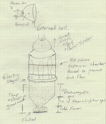
Figure 10: Overview non-radiation concept, possible electromagnet and micro baffling to keep particles opposed to vacuum
Containing xenon streams at these energy and mass levels may prove to be easier in shorter plume capture distances. The geometry may take on different proportions than illustrated above. Chambering and clearing vacuum will have to be experimentally determined. We essentially run the ion thrusters in small vacuum chambers currently on earth and can vacuum the chamber. In space we can use filters in the expansion tube to keep the appearance of space vacuum. I could also imagine a version of the collector that introduces cold xenon or even the other light separation gas into the column to give the fast high energy xenon some company to interact with. Needless to say if we can travel without spending our propellant mass then we can travel further faster with more payloads.
Gamma Ray and High Energy particle Chamber for Xenon collection
To improve further upon this design we can introduce gamma rays or use high energy particles throughout the expansion chamber. The gamma rays essentially help control the plume with no forward momentum loss.
Due to wave particle duality you can essentially affect the space of a particle by treating it like a wave form. We can emit high frequencies into the expansion chamber to cause local interference with exit gas in the expansion chamber. This can be determined by experiment and may include lower wave frequencies that are easier to emit. We have to ensure that our gas is not ionized by these high energy waves and we would have to account for the inner chamber absorption and or reflection of this wave energy. It is possible to create significant interference with low power in a small space relative to these particles.
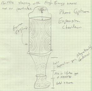
Figure 11: Introduction of gamma ray waves into expansion chamber, non-centrifical
Another expansion chamber concept uses a baffle system with high energy radioactive particles doped into its material. Essentially the radiation particles provide similar interference to gamma rays above except they do not need a power source. Only replacement after their emitting power fades. The specific materials and placement would have to be experimentally determined. With wafer technologies and smaller manufacturing capabilities we will be able to shrink this technology. The radiation would need to be accounted for in the plume, but could technically be vented to space if needed.
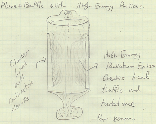
Figure 12: Xenon capture chamber using radioactive isotope, non-centrifugal
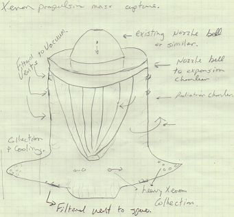
Figure 13: Xenon plume capture using counter-spin and centrifugal motion, with radioactive baffles
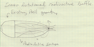
Figure 14: Inner rotational plume recapture
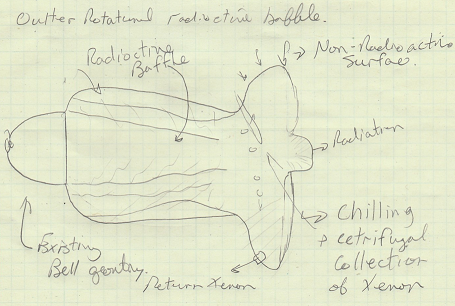
Figure 15: Illustration of outer rotational baffle. Geometry should be experimentally determined, possibly using centrifuge and cooling alone
This phenomenon is due to the boundary conditions at the atomic level as the xenon gas approaches a non-ionizing radioactive surface. Essentially if you fired a xenon atom straight at a heavy non-ionizing radioactive emitter versus another surface the xenon particle would gain buoyancy further from the perceived surface of the material than if fired at a non-radioactive surface. If we are using a heavier radioactive isotope then the effect can be accentuated.
To add to this physics reality, particles at these speeds do not travel on a straight line as we perceive them to. Remember our exit is a plume based on the arc of travel from a nozzle. Well let's further engineer our apparatus and add more bang to the drive above it.
When a particle comes into space it has new momentum as we perceive it. We just shot a mass (xenon) through a fast nozzle. What actually happens is more like skipping a rock on the water. Eventually the particle mass slows down to the speed of its space and energy level. For xenon (relatively heavy) that speed is much slower than light, thus current nozzle thrust from ion propulsion projects in space.
Let's acknowledge that there is space vacuum around our vehicle. Now let's use this vacuum to essentially pull a more perfect vacuum into our plume bell. Essentially if our apparatus is properly engineered we give the plume a vacuum pump geometry and cavity for the plume to expand into. The further this is drawn down from space vacuum the more effective it becomes. Your exit thrust would increase as the particle has a higher theoretical exit velocity than the space around the vessel. You essentially extend your plume further than the space vacuum around it would, thus increasing arc lengths gaining even more MV.
Experiment would need to determine the apparatus. Monitoring of your plume length, chamber temperatures, and cooling temperature in the centrifugal collector is crucial. A shutdown sequence would start at the top. A startup sequence would start at the bottom.
At these speeds particles from radiation sources have hitting power and measurable effects the closer you get to the surface. If you consider both wave vacuum energy as well as the duality principle we can leverage temperature and cooling effects as well as certain geometry to trap our propellant. We may introduce cold xenon or other gas at the center of the centrifugal bell to create more cooling effect and energy neighbors.
The added density throughout the chamber apparatus causes more particle interactions through turbulence and ultimately slow the xenon down more with each random interactions keeping it moving in the right direction. It is important to clear the plume of any particles. This rotational apparatus keeps an "open to vacuum" appearance to the gas particle as it first leaves the thruster and must be experimentally optimized.
If you were to be a purest in the conservation of momentum you'd say the heavy exit xenon transferred any negative momentum to particles along the way which then transmitted to other particles along the way and you cancel your thrust. In actuality you've induced local atomic level turbulence, and temperature gradients in particle terms, or wave energy as vacuum turbulence in your expansion chamber, thus slowing their negative momentum by heat or energy interactions.
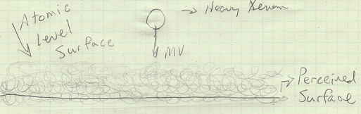
Figure 16: Illustration of perceived surface and atomic surface with a wave energy
Below illustrates a heavy xenon atom fired straight at a non-emitter, at the atomic level it would have more localized atomic interactions in the negative momentum direction.
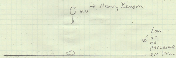
Figure 17: Atomic and perceived surface of the material with a non-emitting surface
You also enhance the effects of this perceived surface area interaction by temperature. The effect being similar to above. These surface level interactions at different temperatures and energies are why we use thermo paints, reflective materials, and black surfaces.
Chemical rockets: No problem. Introduction of Electrostatic Exhaust concept.
One we see every day, a smoke stack. They have large geometry and extend far into the sky emitting whatever we've put into them. Many chemical scenarios I could mention are nastier stuff than carbon. We'll discuss CO and CO2 for a couple of reasons. 1. the global warming initiative, and 2. we can.
The main problem with the carbon problem is industry says hey we built this fancy carburetor (plant), let's just put headers on it. Well so much focus has gone into the other end of the equation that they can't trap carbon from CO2?
My solution capture everything leave some O2 if that is what the environment needs, covert more of it to O3 if that is what the environment needs.
At the top of the stack our ultimate goal is to emit heat and O2. Good news we already have hot CO2 and other carbon gases to work with. As they flow into our new expansion chamber, the MV is easily controllable in this scenario and gravity gives us help along with centrifical motion.
As the expansion chamber might take on some centrifugal geometry we have a hot gas pocket of carbon waste more or less spinning inside. We introduce a baffling system in our expansion chamber. Purpose catch carbon emit O2. This baffling could be fixed to our structure as our purpose of its apparatus is to get the gas cloud mass spinning around and passing through electrostatic or magnetically charged filters. These particles are then simply ionized from their oxygen by the prescribed voltages that you give the apparatus and the heat of their steam and ionization energy.
When these ionization events happen you may see an ionization glow at high flow rates or accumulated little lighting zaps. The result of the ionization if properly engineered is the release of a carbon molecule from the O2, which we refer to as oxygen. If your ionization process creates O-2 , then the O2 will possibly be re-neutralized by static interactions of the exit apparatus.
Our geometry pulls the carbon at these temperatures and pressures statistically further away from the middle as the hot O2 heads towards the top and out our vent. The carbon collects as it is cooled and settles as a dark black soot or sludge. The plant could design this separation system somewhere other than the top of the stack.
We obviously haven't accounted for everything in the plume. We may need to adjust for operating conditions and add some engineering and the geometry for it. Ultimately the exhaust stack should be closed and capture everything. We definitely have the technology to do it and the ionization of particles is well known, predictable, and based on well known elemental characteristics.
Another petro chemical rocket: automobiles
Automobiles contribute most to our carbon pollution problem. Their exit nozzle is at this point not needed for propulsion so why have one. Engines operate on a basic concept. Air mixture in the front with a gaseous fuel (gasoline) is forced through a mechanical air pump where spark and combustion are used to perpetuate the spinning of the motor. Horse power is more or less based on cubic inches and how fast you can combust and flow your gas and air mass through the apparatus.
2 C8H18 + 25 O2 → 16 CO2 + 18 H2O
Well again there is much consideration and fanfare about front side of the equation, but let's just put headers on it, because the rear wheels come before the tailpipe.
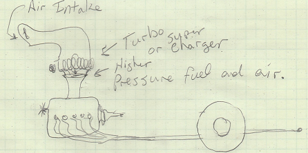
Figure 18: Forced air and basic motor overview
My answer, have a new electrostatic exhaust system catch your carbon and emit O2 and some water vapor.
For the everyday non-performance version of this we will depend on a stationary electrostatic baffling system similar to how you might see mufflers today. Ours however would come with a power connector as well as inlet and outlet ports for your vehicles new carbon capture system. For carbon capture after the ionization process we would leverage a soot trapping geometry along with an oil bath to absorb the waste carbon. As your waste carbon gets more and more used you simply replace it with a fresh batch of waste oil. This old oil should be as easy to recycle at gas stations as the gas is to put in it. Then of course if the refineries cap their stacks would end up in dry waste carbon or waste sludge. Not in the atmosphere. Another place you could put this sludge is into our oil reserves. Technically we can re-refine oils and may find another use for this stored carbon like paving roads or carbon graphite structures.
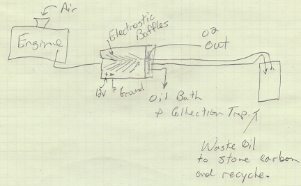
Figure 19: Illustration Electro-Ionizing exhaust and carbon capture in waste oil
How much can your waste oil hold? Good question, it will most certainly look black. The holding capacity of different oils and volumes would have to be determined. The waste oil would have to be analyzed and the bigger your fuel tank the bigger your waste tank generally speaking. You may apply cooling to the waste oil to enhance effects and make it last longer. Ultimately you size your system to replace it with an engine oil change.
Sure we might integrate sensors into our engine control to properly tune your engine performance, or our device may simply detect higher carbon and take it out if we engineer it to. Un-burnt fuel, no problem our ionization micro baffles re-combust them efficiently with their millions of tiny arcs of electricity. Safer and more efficiently.
Now let's talk about performance and efficiency.
A naturally aspirated motor, meaning no turbo or super charging, takes air at atmospheric conditions and then exhausts that combusted air to atmospheric conditions. The operating pressure difference between the top of your motor and the exhaust greatly affects your engines performance.
To increase the power of the motor one common upgrade is to add a turbo charger. Turbo chargers increase air pressure on the intake side of the motor thus giving your engine a bigger pressure gradient, significantly adding horsepower and efficiency to the engine. The turbo boosted air is more dense, thus more on the O2 side of the equation above.
If you use the performance version of our exhaust apparatus you get a similar effect. The performance version of our apparatus uses a stack of counter rotational air baffles through electrostatic geometry, then traps the carbon into your carbon waste oil.
So what is the effect of lowering the apparent exhaust pressure of your motor? A good one, if your system is engineered for it. Obviously engine sensors and controls would need to account for it. On a naturally aspirated engine the effect of lowering the exhaust pressure does several things. It removes heat, increases throttle response, and makes the air coming in at atmosphere look much more dense. The engine idles at much lower fuel rates and essentially better efficiency.
In high performance and factory designs this exhaust feature can be integrated with engine and throttle controls for optimized and experimentally determined benefits. For do it yourselfers there may be some kits that tune these.
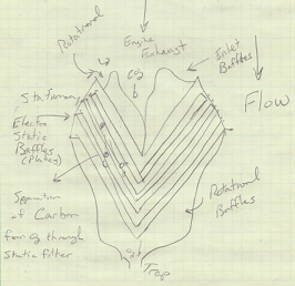
Figure 20: Concept of inner rotational baffles, the apparatus would stack in like cones. The upper and lower are rotational in the inlet and outlet flows driven by the rotational attachments and electric motor assembly. Voltages to electrostatics and motors from vehicle power source.
Over 100 years of combustion engines, let's finaly cap the exhaust we can engineer this.
Performance aside if we put this mixture through a 3/8 inch fuel line and a 4-inch air breather we can get it back out. What if we consider the H2O in the stream that we have to work with? So rather than an oil soot bath we continue to use physics and gas separation points. We vent the O2 that we took from the atmosphere in the first place. And use a long flow chilling and condensation apparatus to condense the hydrocarbon vapors back to your fuel tank. Running out of gas isn't a problem anymore. When you are running low you simply idle until your injectors have enough fuel source to go.
The size of the apparatus can easily fit in a vehicle chassis, as well as the systems to run it. The mastery of cooling, pressure, and heat gradients are at engineered precision. The properties of well known gases and their elements are easily understood and applied.