Now back to space.
Improve current launch, delivery, and recovery, momentum lift column
How can we enhance current launch and recovery concepts? When I look at a rocket being blasted into space I see a ton a wasted energy with very small payloads. The following concept increases payloads, enables landing, and adds safety to both using ∆T and geometry to create and induce helpful air flows.
First let's create a lift toy. We will start with a momentum disc.
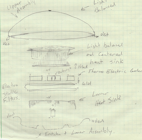
Figure 21: Lift toy for atmosphere, momentum disc, no moving parts.
First thing throwing discs are generally heavy and rather thick so they can be thrown farther, ours has a different purpose. Our momentum disc is being designed to float more like a bubble. So our upper assembly is light possibly even a cloth or kite material. Our lower assembly may be more plastic like to hold the apparatus together.
Between the upper and lower assembly we leverage several technologies to give this apparatus lift. We use circular and balanced geometry to leverage natural level spinning effects. We use and upper and lower heat sinks in geometrically pleasing configurations as above. Between these two very light heat sinks we leverage a thermo electric conductor to create a very large temperature gradient between the lower sink and the upper sink.
We also choose geometry that allows the warmed air to pass through from below the apparatus and heat sinks in pleasing ways.
The natural spinning and warming of this apparatus will tend to allow colder heaver particles to gradually move away from center and out the outer centrifugal escape vents. If we keep the right mix of lighter warmer air we further enhance our buoyancy by keeping colder air below us. The lower heat sinks and their air passages are designed to extend through the lower assembly. The effect of keeping cooler air below us has a benefit. We appear to be on a heavier air mass. It also increases the heat and lift effects as this air expands in our lift geometry.
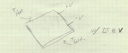
Figure 22: Thermo-electric heating/cooling plate. Also used in temperature sensing and many applications
Thermo electric cooling wafers have been in use and refined over the years. They look like a small metal square with 2 wire leads or sometimes simply look like a temperature sensor. When you apply voltage to the wire leads at room temperature one side gets hot, the other side gets cold. There are various applications and affordable manufacturing and supply. The temperature gradient depends on your design and the voltages that you apply to them.
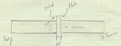
Figure 23: Thermo-electric will take the metal heat mass and make a temperature gradient
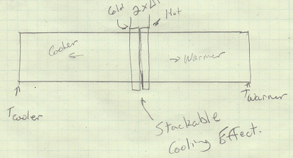
Figure 24: At 2 x the power, i.e. stacking
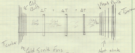
Figure 25: Illustration with 3X and accentuation of the heat gradient across the apparatus
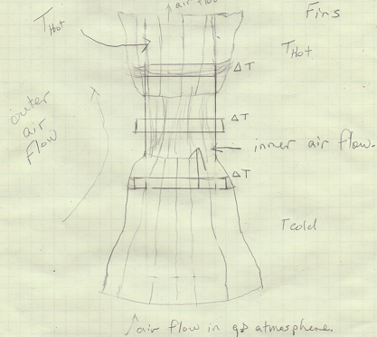
Figure 26: Upright illustration with accentuated fins in air flow pleasing direction
When we turn this device on the thermo-cooling and heat gradients start to move out to their equilibrium with the battery voltage, and the top air gradually becomes warmer compared to the lower air. The toy's light upper lift surface would appear to start filling and the toy might start to spin and glide on the floor. If the temperature variant and the ion filter is doing enough work then your total lift is enhanced.
This disc toy would continue to spin and rise until the battery power level and weight leveled off. As the battery lost charge the toy would spin down with the decreasing ∆T, if uninterrupted by a gust or power line.
Further with thermoelectric cooling I can double stack the thermal plates and get a larger temperature gradient from cold to hot. Ultimately I can stack a temperature gradient of hundreds of degrees if my design and power can produce it, just in the space of this toy.
So now we can perceive upgrading our toy with a remote control. One simple controllable motor that can rotate a small mass about the overall center of mass would suffice and possibly some controllable vents to maintain lift.
A more advanced version of the apparatus could control battery usage, or maintain a light solar array on its lift panels. A hobby device could find other ways to provide ∆T.
I can envision a version of this toy sealed and equipped for use in a vacuum that would translate motion when released in space by our space station crew. This translation of motion would be induced simply by the ∆T with the cabin air that the apparatus was released with venting none to space.
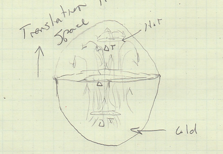
Figure 27: Astronaut version of toy, illustration of internal lift column using ∆T
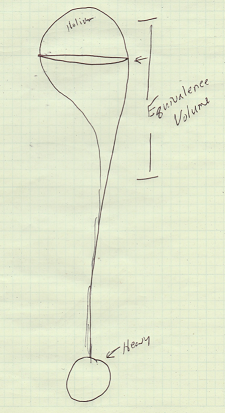
Figure 28: Lift balloon illustration
Let's consider the illustration above Figure 28. A helium balloon will lift a heavy weight if given enough volume to displace in the local atmosphere. Figure 29 below illustrated a hot air balloon lift.
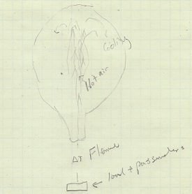
Figure 29: Hot air lift balloon, hot air makes upward column about center line and cooling about edges
Let's now use this concept to enhance lift on hot air balloons. If you notice we typically leverage only the displaced air volume. There is a huge large air mass with swirling momentum overhead. So we engineer a lift enhancement system with a center internal lift cap, external outer lift ring air foil, and a stand off from the top of the hot air apparatus to keep this device in location and aid in distribution of increased lift.
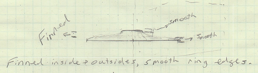
Figure 30: Lift cap geometry from front or side view, conceptual
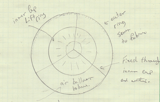
Figure 31: Illustration of lift cap geometry with respect to outer lift ring. Geometrically centered with the lift of the balloon
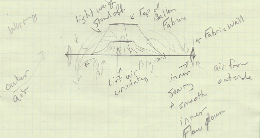
Figure 32: Side view a balloon lift cap assembly and illustration of air flow and lift increase
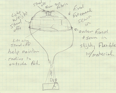
Figure 33: Illustration of lift ring and lift cap apparatus with balloon, weight, and heat source, I can devise a lower ring assembly further improving lift and stability of the overall apparatus. Outer lift rings provide stabilizing air foil with outside air, inner leverages and accentuates the swirling flow of hot air mass in the balloon.
As you can see in the illustrations above we are improving upon many natural geometries and momentum tendencies of the lift column. Using vertically mounted fins I can also devise ways to better steer your balloon with a remote control. Let's now look at a heavy lift optimized vehicle with all that we know.
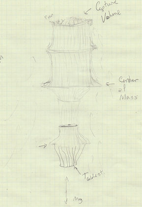
Figure 34: Illustration of overall heavy lift with capture assembly, temperature gradients and outer lift column of air. Accentuation of design for lift due to induced air flows
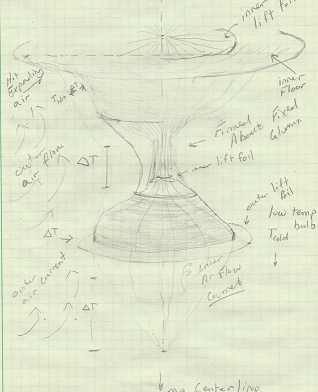
Figure 35: Illustration lower assembly and heavier lift concepts using ∆T gradients to create air flows
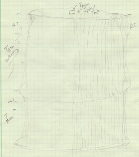
Figure 36: Outer capture capitalizing on outer lift column using its own finned heat from the apparatus and air current inducement using temperature differentials
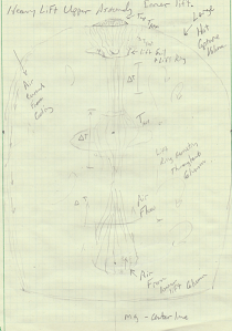
Figure 37: Illustration of heavy lift internal upper capture volume accentuating and extra lift with internal lift column
For true heavy lift we may circulate THOT and TCOLD throughout our apparatus as well as accentuate features of catching both internal and external lift columns. A truly heavy lift should be designed for stiffness, stability and vertical operation in atmosphere. Your lift columns and geometric enhancements for lift should be designed in multiples of three for better stability. A table needs three legs to stand on. Thrust and lift are similarly stabilized by using 3 or more columns about your center of mass.
Large air ship design gains the benefit of larger capture volumes and lift surfaces. Also larger vessels gain efficiency with much larger, longer, and controllable air columns. As you control and channel air flow on the outer part of the vessel you capture all the lift and buoyancy effects of expanding warming air with lift foils against the hull of your ship. The great news is that we can provide large ∆T anywhere and over any distance. Further we can make a heat mass look much larger by using vertically aligned light weight fins. Internal capture volumes should also be designed to capture the circulating lift momentum of their volume. The mass momentum from inner up-flows are as important as the volumes of mass that they offset.
Steering a mass momentum drive in space
Steering of a column concept mass momentum drive will be performed at thrust by controlling steering mass about your ships center of mass. Nozzles are always pointed down for efficiency and beneficial inertial reasons.
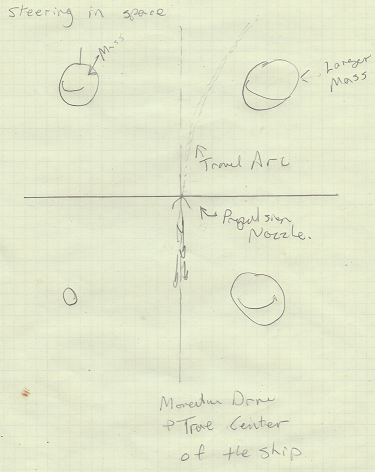
Figure 38: Steering will be based on controlling ships center of mass about your thrust column. This illustrated steering to the right with forward and behind masses.
Plume capture, it's wasted energy otherwise
Plume re-use may be the technology to develop. With this momentum conservation and redirection concept via state physics we can increase thrust power, weight, and volume to our space craft. I can think of various and many applications to provide more fuel efficient lift and travel using less power.
This can also lend to theoretical speeds faster than light, i.e. no speed limit. The MBVT always adds to positive momentum.
Back to Xenon and other propellants
Xenon as illustrated above is a propellant used through solar ionization to propel vehicles through space. It is hard to find and requires storage management systems. We are working with a gas and only a gas. I could see xenon being more useful in a series of momentum propulsion columns. Possibly just using the heat differentials of a sun facing and non facing apparatus.
You could also use xenon with a nozzle and an integrated positive momentum storage and capture volume as illustrated below in figure 39. Provided you could sustain TCOLD and provide pleasing geometries this makes your thrust have a much more efficient and sustaining effect.
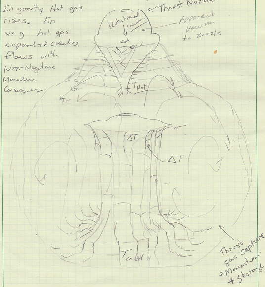
Figure 39: Integrated nozzle capture in sustained positive momentum volume.
Iron is perceived to be heavy in a much smaller space.
What about iron? Our earth has plenty of it. We can do many things with it. Electrically we can arc voltages right to it. It is easy to use for heat gradient functions and face it, we know a lot about it. We can use more of its potential as a resource throughout its different phases, i.e. solid, gas, liquid, plasma. Mars has it too!
We have been shooting cannon balls, bullets, and plasma arcs with iron for a long time. If you look at a welder you see sparks flying. These are un-nozzled bits of iron. We can absolutely recapture those in a microwave or reheat column as mentioned above. I can envision stacked teams of momentum drive columns with either nozzles or pools leveraging ∆T. Want more MV just add lead.
Ultimately if we want to penetrate space and step aboard a space yacht, we will need to go big. As the momentum physics concepts bring to light we can keep our mass. We can also launch and take bigger things with us. If we can take on some cabin space as well as some rotational geometries we can provide better quality of life as well as better science and research.
At the atomic level this can ultimately be done in the palm of your hand. Using wafers with tiny dimples, layers of materials with anodes and cathodes can arc through these dimples firing mass particles at near the speed of light.
Using state and momentum physics with pressure, apparent vacuum, and temperature control we can catch these in very short distances.
Improve greenhouse gas emissions and decrease dependence on fossil fuels with these techniques on earth. Engineer around these concepts to get big fast things to space.
With the momentum drive concept, your ratio of dead weight to propulsion mass throughput determines the sustained thrust that you can maintain. Using momentum columns that account for momentum and state physics to provide thrust with recapture is possible.
There is no speed limit. As you go faster you go faster. The better you can control your rotational counter spins and vertical stiffness of the overall structure the higher sustained g you can maintain. Thrust will be more a comfort level for the occupants and their ability to reach for the throttle.
Please feel free to comment, review, or respond to this article. We look forward to your messages.